Hi, I'm trying to replicate this project, the final goal is to control 4 servos with a joystick. I have a complex problem that I don't know how to troubleshoot.
I started by soldering the joystick board. At the moment I am trying to check the functionality of all components. Currently I cannot load any program onto my Arduino via USB. At the same time I receive data from one axis of one of the joysticks via Serial Port (I didn't upload any programs since I bought this Arduino board).
This situation is not affected by what program I am trying to load, nor by the fact that an external power source (9V battery) is connected/disconnected. You can see the board layout in the photo. The pin connections are following:
X, Y axis of joysticks connected A0-A3
D13 — CSN
D12 — CE
D5 — SCK
D7 — MOSI
D4 — MISO
The sketch I'm trying to download and use from this library is Optimized high speed nRF24L01+ driver class documentation: Optimized High Speed Driver for nRF24L01(+) 2.4GHz Wireless Transceiver, "Getting Started".
My final goal at this stage is to output information on all 4 axes of the joysticks, as well as information from the NRF module (I understand that I will not be able to create connections without the second module, but I want to at least get an understanding that my NRF module is soldered correctly ).
The current goal is to understand why I can't load the program onto the Arduino and how to fix it. I have another nano if needed, I haven't unpacked it yet.
I've uploaded detailed photos of my board on imgur because I can not upload more than 3 images here. The link: Imgur: The magic of the Internet
Here is what I'm getting through serial port:


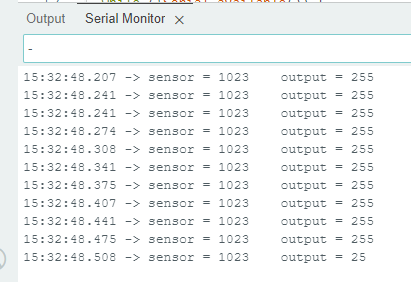
I have this data (which react to movement of left joystick on up/down movement) until I'm trying to load new sketch. At this moment serial port looses connection.
The sketch I would like to use (I know that CE_PIN, CSN_PIN are different in my case, this is an example):
/*
 * Copyright (C) 2011 J. Coliz <maniacbug@ymail.com>
 * Updated 2020 TMRh20
 *
 * This program is free software; you can redistribute it and/or
 * modify it under the terms of the GNU General Public License
 * version 2 as published by the Free Software Foundation.
 */

/**
 * Channel scanner and Continuous Carrier Wave Output
 *
 * Example to detect interference on the various channels available.
 * This is a good diagnostic tool to check whether you're picking a
 * good channel for your application.
 *
 * Run this sketch on two devices. On one device, start CCW output by sending a 'g'
 * character over Serial. The other device scanning should detect the output of the sending
 * device on the given channel. Adjust channel and output power of CCW below.
 *
 * Inspired by cpixip.
 * See http://arduino.cc/forum/index.php/topic,54795.0.html
 */

#include "RF24.h"
#include "printf.h"

//
// Hardware configuration
//

#define CE_PIN 7
#define CSN_PIN 8
// instantiate an object for the nRF24L01 transceiver
RF24 radio(CE_PIN, CSN_PIN);

//
// Channel info
//

const uint8_t num_channels = 126;
uint8_t values[num_channels];

//
// Setup
//

void setup(void) {
  //
  // Print preamble
  //

  Serial.begin(115200);
  printf_begin();
  Serial.println(F("\n\rRF24/examples/scanner/"));

  //
  // Setup and configure rf radio
  //

  radio.begin();
  radio.setAutoAck(false);

  // Get into standby mode
  radio.startListening();
  radio.stopListening();
  radio.printDetails();

  //delay(1000);
  // Print out header, high then low digit
  int i = 0;
  while (i < num_channels) {
    Serial.print(i >> 4, HEX);
    ++i;
  }
  Serial.println();
  i = 0;
  while (i < num_channels) {
    Serial.print(i & 0xf, HEX);
    ++i;
  }
  Serial.println();
  //delay(1000);
}

//
// Loop
//

const int num_reps = 100;
bool constCarrierMode = 0;

void loop(void) {
  /****************************************/
  // Send g over Serial to begin CCW output
  // Configure the channel and power level below
  if (Serial.available()) {
    char c = Serial.read();
    if (c == 'g') {
      constCarrierMode = 1;
      radio.stopListening();
      delay(2);
      Serial.println("Starting Carrier Out");
      radio.startConstCarrier(RF24_PA_LOW, 40);
    } else if (c == 'e') {
      constCarrierMode = 0;
      radio.stopConstCarrier();
      Serial.println("Stopping Carrier Out");
    }
  }
  /****************************************/

  if (constCarrierMode == 0) {
    // Clear measurement values
    memset(values, 0, sizeof(values));

    // Scan all channels num_reps times
    int rep_counter = num_reps;
    while (rep_counter--) {
      int i = num_channels;
      while (i--) {
        // Select this channel
        radio.setChannel(i);

        // Listen for a little
        radio.startListening();
        delayMicroseconds(128);
        radio.stopListening();

        // Did we get a carrier?
        if (radio.testCarrier()) {
          ++values[i];
        }
      }
    }


    // Print out channel measurements, clamped to a single hex digit
    int i = 0;
    while (i < num_channels) {
      if (values[i])
        Serial.print(min(0xf, values[i]), HEX);
      else
        Serial.print(F("-"));

      ++i;
    }
    Serial.println();

  }  //If constCarrierMode == 0
}
I would enormously appreciate any help that you could provide. This is my first hardware/low-level software project, as I'm learning to become an embedded engineer. I am hoping for your patience. Thank you for the help.
7 posts - 2 participants